This project has been popular and will certainly improve your visibility. Read through the instructions before starting. There are many variations on how to install so think of this as just a suggested method.
LED Controller - $3 on Amazon and some LEDs that come in many colors (about $10). 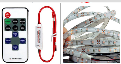 Wiring is just a matter of connecting red wire to red and black to black. With no controller, just install LED on outside, drill a small hole to pass the wire through and connect. The LED controller is an option that requires a wire run from one side to the other. Two LED controllers means no connecting wire needed. Mark ran the LED strip from the front turn signal to the tail light with a small hole drilled to pass the wires through to the inside. [note: you can also loosen the tail lights and feed the wire through the hole to avoid drilling] The LEDs have a peel-and stick backing that works well for a while but probably should be reinforced with a better adhesive. You can run the str 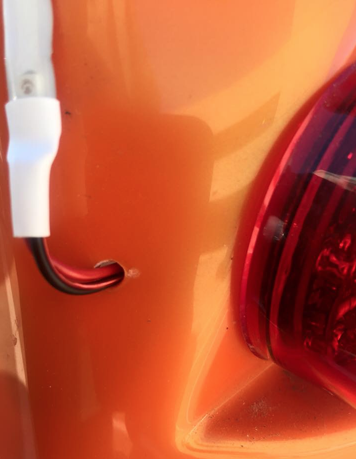 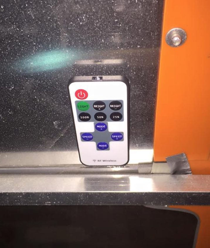 Controller remote is attached with 3M Heavy Duty Fastener (like a super-duty velcro) to the bottom of the solar panel just above the windshield. You can mount it anywhere you want. I didn't want it too obvious to curious hands. Inside of hole to pass wire through from outside. Note that the light to the LED wires goes up to that black electrical tape. In the 1 controller configuration, you see the LED wires (red & black coming through hole), controller's output wires (red & black from left of picture), and my wire that connects this to the right side (silver and gold speaker wire) are joined together in a pair of butt-end splices. Because of the vibration in an ELF, I strongly recommend soldering the wires together, then covering with electrical tape. I would not trust crimp connectors in this application. The full set of wires is then cable tied to the existing wires to eliminate mechanical pull against the splice. 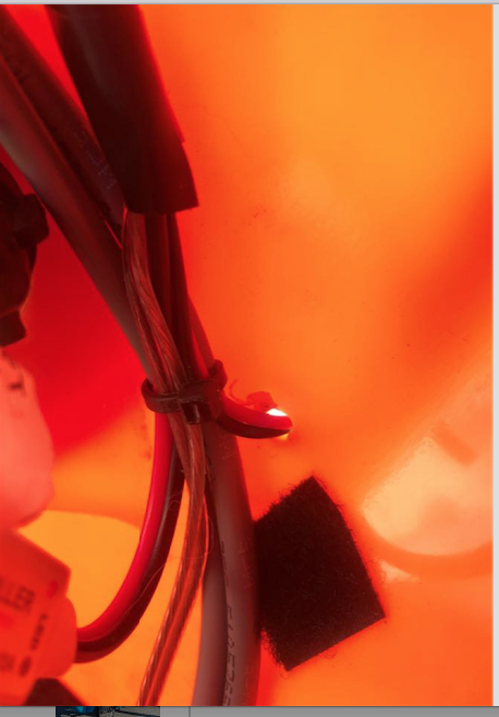 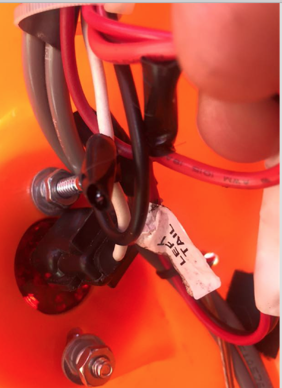 LED controller wired in with connector wire run to the other side. Note both sets of butt-end solder splices are cable-tied in place. ----------------------------
Larry's comments. OK this was easy - no drilling holes, no soldering, and no cutting of ELF wires. For power I used the wires that went to the horn (never was a big horn user) and attached some speaker wire. I fed the wire to the back and out the tail lights (No exit hole drilling). I added a wire to bring power to the tail light on the other side too. I stuck on the strips and voila it was done. What about the $2 RF remote controls? I saw 1 work during a dry run but it stopped working by the time it was a in place. The second one never worked. I'll order a few more and add them in the Spring when they arrive from China. Haha. I also would caution you avoid pulling the strip
while sticking it to the Elf sides. I must have pull it too hard trying
to keep the line straight and it broke so I had to cut it off at that
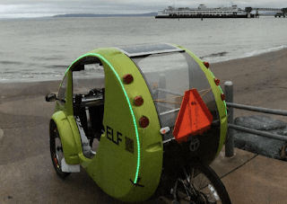
point. A bit shorter than I wanted. Other finished products
[source: Mark Eakin FB post]
|
Upgrades / Add ons >